New and old technology usually don’t work well together. Trying to connect your Betamax video player to an OLED screen may be a challenge. It will work, but how? The same principle applies to traditional firewall setups in the cloud. With the virtualization of the networking stack not all features available in physical networks are present. This includes the use of floating IP addresses or Broadcast traffic and that influences the implementation of HA architectures.
When deploying HA architectures, there are a few options to provide failover:
- Azure API Route Table Managed
- Azure API floating IP managed
- Load Balancer managed
The first option uses two route tables, one active, one passive to switch the active gateway IP for all services running on a VNET/Subnet.
The second option uses a secondary IP address on the FW’s that can be moved between an active and a stand-by FW.
The third uses an Azure Load Balancer to act as the gateway IP for all workloads which then forwards the traffic to the active FW (or active/active).
The problem with the first two options is that failover itself is usually slow. The FW must instruct the failover, which is essentially a “reconfiguration” of Azure services through a new deployment. Depending on how fast that deployment is completed, the traffic flows will be down for several minutes. Furthermore, it doesn’t allow for an active-active configuration where both firewalls are operating at the same time.
2-Legged FW’s
Let’s build our HA architecture and start with 2 FW’s, load balanced externally:
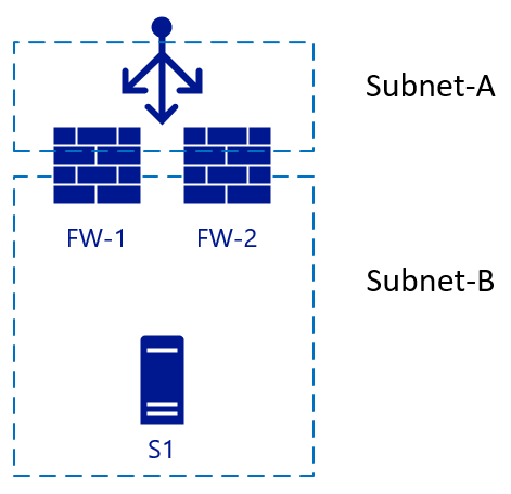
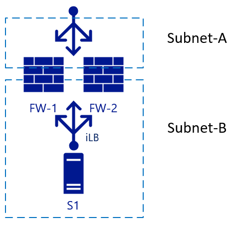
This is a simple setup. For inbound traffic, a packet hits the load balancer, which chooses a FW which then sends the traffic to the server. If FW-1 has SNAT enabled, server S1 will see the traffic coming from FW-1 and therefore send the reply to FW-1 as well. Failover can happen quickly to FW-2 in this scenario. For outbound traffic, we could add another load balancer on the internal side, so when server S1 initiates traffic the same principle will apply. Traffic hits the internal LB (iLB) which then chooses a FW which then performs NAT translation for external resolution:
So far, no problems yet.
3-Legged FW’s
Problems start to arise when we add another interface to the firewall, and we need to disable NAT translation between “internal” zones. In our case, Subnet-B and Subnet-C:
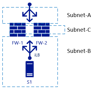
If we want to have L3 routing between the two subnets we will see that the load balancers are going to be in the way, again the same architecture in a different view (where the iLB’s are linked to a specific NIC on the FW’s):
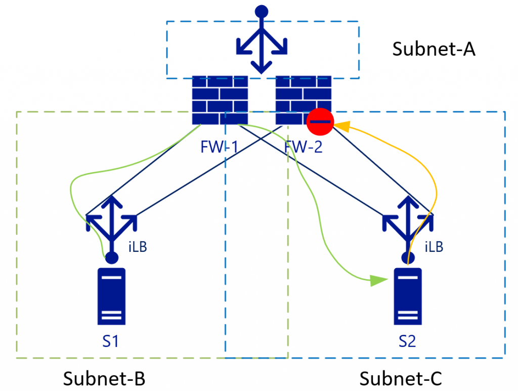
With L3 traffic (without NAT), S2 will see the S1 IP address as the source address and therefore will send the return traffic for Subnet-B (to which S1-IP belongs) to the iLB in Subnet-C. As iLB in SubnetB and iLB in subnetC do not synchronize their session states, depending on the load balancing algorithm traffic could end-up on FW-2. FW-2 by default doesn’t know anything about the initial (green) packet and will therefore drop the connection.
Some firewall vendors try to keep a connection state between the firewalls, but they would have to have almost instant synchronization to be up-to-date on the connection states.
So how to deal with this problem? The best way is to eliminate it. In our example this means eliminating Subnet-C, which brings us to Virtualized VNET’s advantage 1.
Hosts in a Subnet can be isolated by using Network Security Groups:
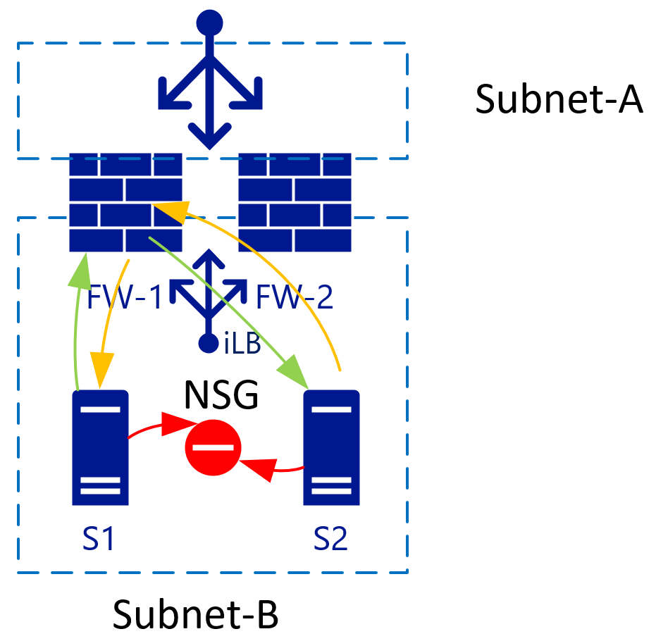
If you have 2 VM’s in a single subnet, you can apply an NSG that isolates traffic between the two. By default, traffic inside a VNET is all allowed. Add a Deny all rule on the NSG, and all VM’s are isolated from each other.
But, say we don’t want to mingle NSG’s and Firewall Appliances? Advantage nr2: VNET/Subnets use a single backend router system from Azure and as such, we don’t have to specify a router IP for each subnet, but the route destination can be anywhere in the same VNET (or even outside).
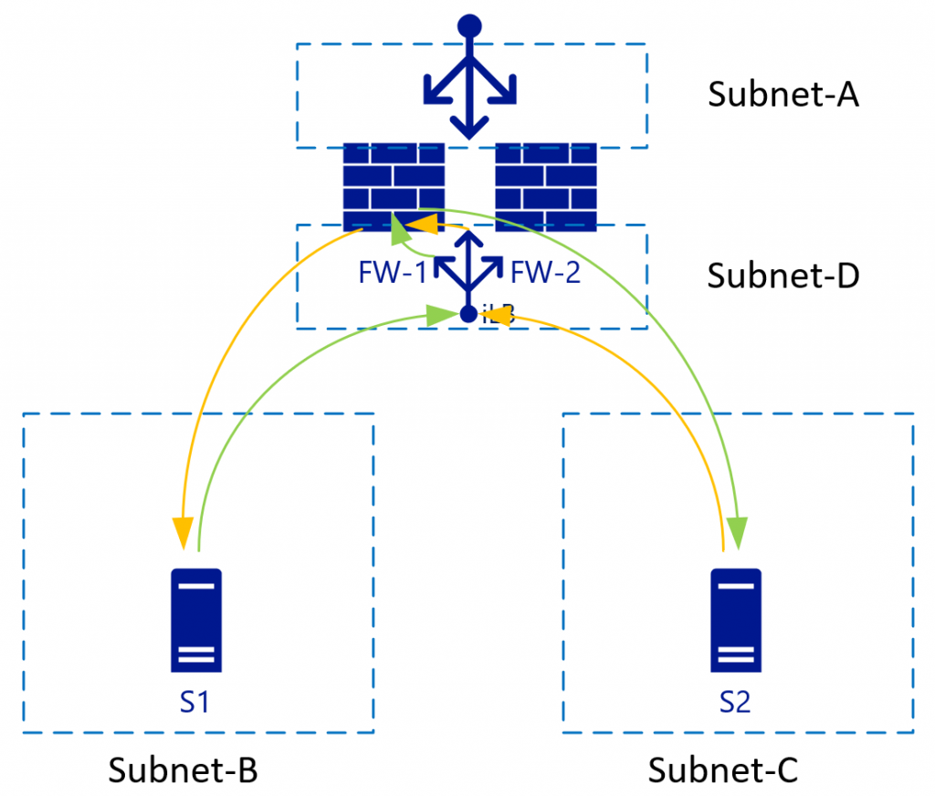
With the virtualized networks, we can control the routes in every subnet. These routes can also point to a single IP in another subnet. In the picture above, that would be the iLB in Subnet-D which load-balances the two firewalls. As S1 initiates traffic (green), it will be load balanced to for example FW-1. FW-1 will then connect to S2 (still green). S2 will send the response traffic to the IP of S1 (as we are not using NAT) and because of the route tables, S2 uses the same iLB IP as it’s gateway. The iLB will be able to match the traffic to the initial session and therefore will always point this traffic back to FW-1, which then sends it to S1, establishing a synchronous traffic flow.
For this to work though, the FW needs to have a route table (internally) pointing subnet-B and subnet-C to it’s default subnet GW (the first logically available IP in the subnet range).
Reverse Proxy services
Let’s say now we want to deploy a KEMP, F5, Netscaler or other reverse proxy service. “Normally” this would be behind the FW, but you can also put it “in-line” with the FW and actually route the traffic through the FW. The advantage of this is that the reverse proxy service would “see” the original IP of the connecting client:
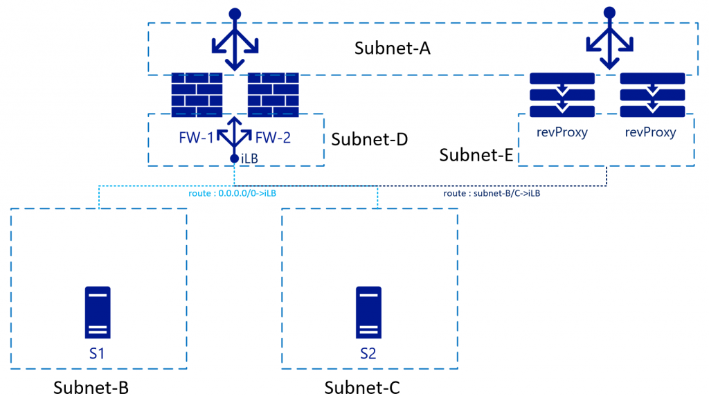
For this, the route tables on Subnet-E need to point Subnet-B and Subnet-C through the internal load balancer. Obviously, you could also remove the FW all together in this network flow and point from revProxy straight to Subnet-B/C servers.
In this scenario you will need to setup SNAT on the revProxy’s as well to avoid return traffic to flow through (and denied by) the FW’s to Subnet-A.
VPN/ER
Bringing us to Virtual Network Gateways / ER Gateways. Due to the BGP/HA available services in Azure Virtual Network Gateways, most architects keep these for other connections. This means that the routing table now needs to accommodate these subnets too. While there is not a big difference to subnet-B/C connectivity, there is now the return traffic, completing the picture:
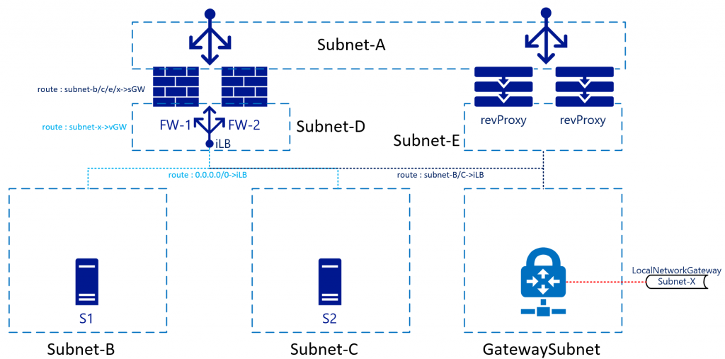
In this architecture, traffic hitting the FW from for example Subnet-B to Subnet-X would be sent to the iLB which sends it to either firewall. The internal route inside the FW will send the traffic back to the SubnetGW (first available IP in subnet-D). You don’t have to send the traffic straight to the Gateway appliance itself, as another route on Subnet-D will have a route for Subnet-X pointing it to the “Virtual Network Gateway”. Azure Networking will take of the actual routing.
Return traffic coming from Subnet-X will be forwarded to the iLB in Subnet-D as the GatewaySubnet will also have a custom route pointing Subnet-B-C to the iLB. Note that Subnet-D is not via the iLB. This will be treated as “regular” inter VNET routing.
While not in the drawing, it would make sense for Subnet-B/C/D/Gateway to also include a route for Subnet-A pointing it to the iLB. This to avoid the “regular” VNET routing to bypass the FW’s. This as Subnet-A is “just another subnet in the VNET” according to the Azure networking stack. It will not treat Subnet-A different although you treat it is DMZ/Internet/etc.
Summary
In short, the way you treat firewalls in your on-premises networks, with as many interfaces (virtual or physical) is not the same as you would in Azure. You still can, but there are better ways to ensure you can minimize fail-over downtime, have Active-Active implementations and “clean” routing tables.
https://docs.microsoft.com/en-us/azure/load-balancer/load-balancer-ha-ports-overview